 EN
EN


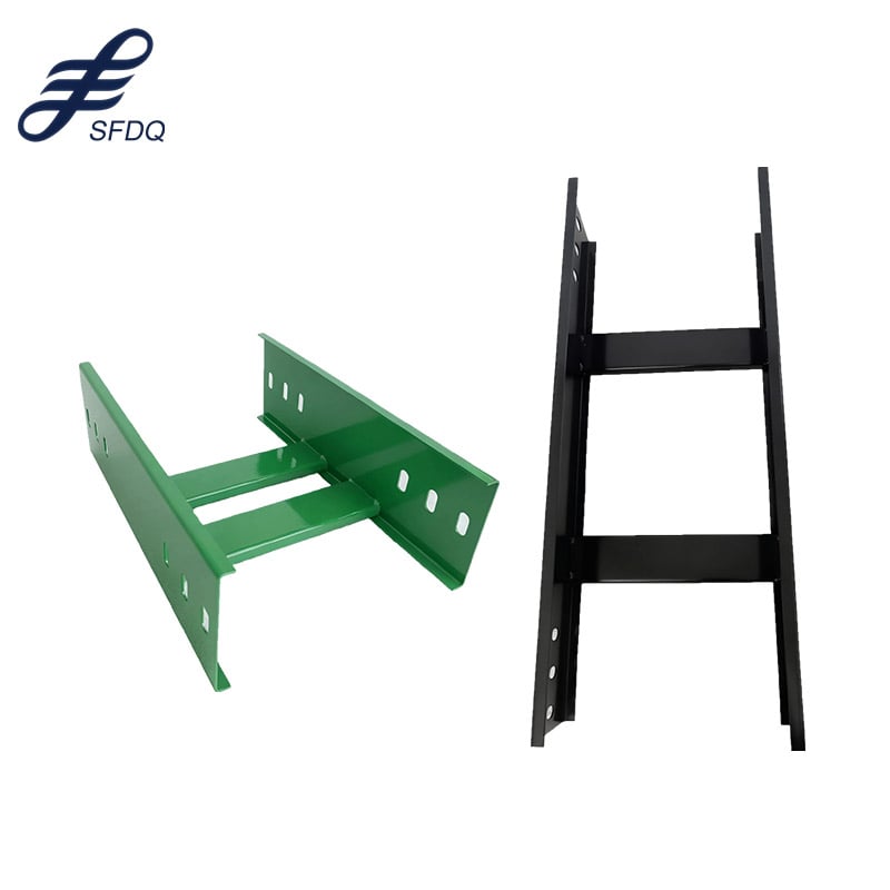
A ladder cable tray is one of the most widely used cable management solutions in industrial, commercial, and infrastructure projects. Its open-rung design promotes airflow around cables, simplifies inspection, and supports heavy cable loads across long horizontal and vertical runs. Whether you are working on a new build or a retrofit, understanding how to install a ladder cable tray correctly is critical to long-term performance and safety compliance.
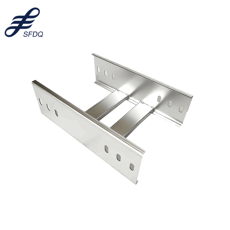
This practical guide walks through every major stage of ladder cable tray installation, from initial planning and layout to mounting hardware selection, assembly, and final finishing. Following a structured approach saves time on-site, reduces rework, and ensures your ladder cable tray system meets both project specifications and relevant electrical codes. Keep this guide close during your installation planning to avoid the most common field mistakes.
Planning and Layout for Ladder Cable Tray Installation
Site Assessment and Route Mapping
Before any ladder cable tray component arrives on-site, a thorough route survey is essential. Walk the entire cable path and mark proposed support locations, noting any obstructions such as HVAC ducts, structural beams, or existing conduit runs. A clear route map lets you calculate the exact number of ladder cable tray straight sections, bends, tees, and reducers required. Accurate take-offs at this stage prevent costly ordering errors and delivery delays.
When mapping the route, account for the minimum bending radius of the cables that will occupy the ladder cable tray. Heavy power cables demand wider horizontal bend fittings, while control and data cables are more flexible. Confirm ceiling heights and available clearance above the ladder cable tray to satisfy maintenance access requirements. Document all dimensions and share the route drawing with the project engineer before placing your material order.
Selecting the Right Ladder Cable Tray Specifications
Ladder cable tray comes in a range of widths, typically from 100 mm to 900 mm, and in standard section lengths of 3 m or 6 m. Select the width based on the total cable fill area, leaving at least 20 percent spare capacity for future additions. The rung spacing on a ladder cable tray directly affects how well cables are supported; a 300 mm rung pitch suits most power cable applications, while a 150 mm pitch provides tighter support for smaller cables.
Material selection is equally important. Hot-dip galvanized steel ladder cable tray suits most indoor and outdoor industrial environments, offering strong corrosion resistance. Stainless steel ladder cable tray is preferred in chemical plants or food processing facilities. For lightweight applications or areas with chemical exposure, a fiberglass reinforced plastic ladder cable tray provides an excellent non-conductive alternative. Always confirm the chosen ladder cable tray material meets the environmental and load requirements of the specific zone.
Mounting and Supporting the Ladder Cable Tray
Support Spacing and Hardware Selection
Correct support spacing is one of the most critical aspects of a reliable ladder cable tray installation. Manufacturers publish load tables that specify the maximum support span for each ladder cable tray width and load class. As a general starting point, support the ladder cable tray every 1.5 m to 3 m along horizontal runs. Reduce this spacing near joints, at changes of direction, and where cable load is highest. Never exceed the published span, as overloading can permanently deflect the ladder cable tray and damage cables.
Use purpose-made hangers, channel brackets, or trapeze frames to carry the ladder cable tray. All fixings to the building structure must be rated for the combined weight of the ladder cable tray and the full cable load. When mounting a ladder cable tray to concrete ceilings, use chemical anchors or expansion anchors sized according to the pull-out load data. Steel channel strut systems offer flexibility because they can be adjusted during installation before final tightening, which simplifies alignment of the ladder cable tray along the planned route.
Assembling Sections and Fittings
Lay out all ladder cable tray straight sections and fittings on the floor before lifting them into position. This dry-run assembly reveals any mismatched components and allows you to pre-cut sections to length. Use a cold saw or angle grinder with a metal-cutting disc to trim the ladder cable tray cleanly; always deburr cut ends and apply zinc-rich cold galvanizing compound to any cut edges to restore corrosion protection.
Connect ladder cable tray sections using the splice plates and bolts supplied by the manufacturer. Tighten splice plate bolts to the specified torque to ensure mechanical continuity and structural integrity. Where the ladder cable tray changes direction vertically or horizontally, install the corresponding factory bend fitting rather than forcing a straight section into a curve, which would stress both the ladder cable tray and the cables inside it. Maintain a consistent top-of-tray elevation throughout horizontal runs so cables lie flat and are evenly supported.
Finishing, Earthing, and Safety Checks
Bonding and Earthing the Ladder Cable Tray
Electrical continuity across the entire ladder cable tray run is a mandatory safety requirement in most electrical installations. Install earthing continuity bonds at every splice joint unless the splice plate design already provides a certified low-resistance connection. At regular intervals, connect the ladder cable tray to the building earthing system using a suitably rated conductor. This prevents dangerous touch voltages from accumulating on the metallic ladder cable tray structure in the event of a fault.
Test bonding continuity with a low-resistance ohmmeter after the full ladder cable tray run is assembled but before cables are laid. Document the test readings and keep them as part of the installation record. A well-earthed ladder cable tray significantly reduces electromagnetic interference on sensitive signal cables sharing the same route, improving system reliability beyond basic safety compliance.
Cable Installation and Final Inspection
Once the ladder cable tray is fully mounted, bonded, and inspected, begin laying cables. Segregate power cables from control and data cables using the rungs of the ladder cable tray as natural division points, or install a center divider if the ladder cable tray width permits. Secure cables to the rungs at intervals recommended by the cable manufacturer to prevent sagging and movement. Avoid overfilling the ladder cable tray, as exceeding the rated fill depth traps heat and reduces cable current-carrying capacity.
Conduct a final visual inspection of the entire ladder cable tray installation before closing out the project. Verify that all supports are tightened, all end caps and edge protectors are fitted to prevent cable abrasion, and all covers are installed in areas requiring mechanical protection. A thorough close-out inspection confirms the ladder cable tray installation is safe, code-compliant, and ready for energization.
FAQ
What is the standard support spacing for a ladder cable tray?
Most ladder cable tray manufacturers recommend support intervals between 1.5 m and 3 m for horizontal runs, depending on the tray width and load class. Always consult the load table specific to your ladder cable tray model to confirm the allowable span for your actual cable weight.
Can a ladder cable tray be used outdoors?
Yes, a hot-dip galvanized or stainless steel ladder cable tray is fully suitable for outdoor installations. Ensure all fittings, supports, and fixings carry the same or higher corrosion resistance rating. In coastal or chemical environments, consider a heavier coating or stainless steel ladder cable tray for extended service life.
How do I maintain electrical continuity across a ladder cable tray system?
Fit manufacturer-approved earth continuity bonds at every splice plate joint unless the splice plate itself is certified to provide bonding. Connect the ladder cable tray to the facility earth bar at regular intervals and verify continuity using a low-resistance ohmmeter after assembly. This ensures the ladder cable tray meets earthing requirements under all fault conditions.