 EN
EN


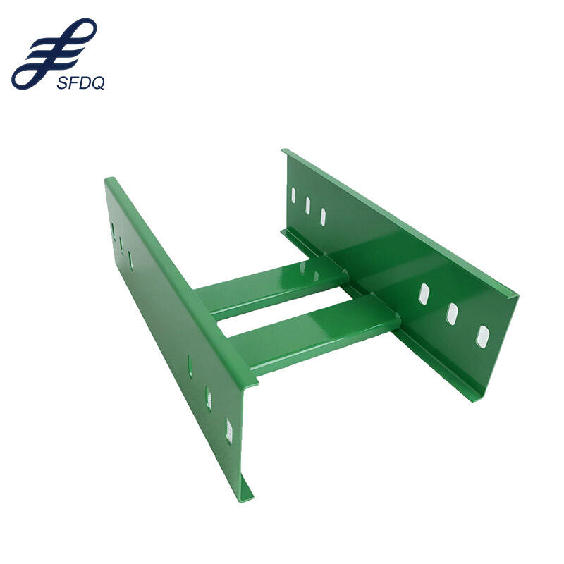
Installing tray cable in cable tray systems requires careful attention to proper routing techniques, load calculations, and compliance with electrical codes to ensure optimal performance and safety. The installation process involves understanding cable specifications, tray configurations, and environmental considerations that directly impact the electrical system's reliability and longevity.
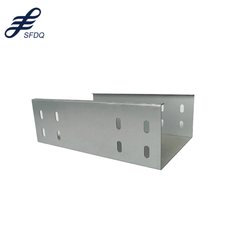
Proper tray cable installation enhances power distribution efficiency while reducing maintenance requirements and operational downtime. Understanding the relationship between cable tray design and tray cable characteristics enables installers to create robust electrical infrastructure that meets both current demands and future expansion needs.
Pre-Installation Planning and Assessment
Cable Tray System Evaluation
Before installing tray cable, a comprehensive assessment of the existing cable tray system determines structural capacity and compatibility requirements. The tray system's load rating must accommodate the combined weight of all planned cables plus a safety margin for future installations. Engineering calculations should account for dynamic loads, thermal expansion effects, and environmental stresses that may affect cable performance over time.
Cable tray dimensions directly influence tray cable routing options and installation methods. Standard tray widths ranging from 6 inches to 36 inches provide different cable capacity scenarios, while tray depth affects ventilation and heat dissipation characteristics. The tray material composition, whether aluminum, steel, or fiberglass, impacts corrosion resistance and electromagnetic interference considerations.
Inspecting existing tray conditions reveals potential installation challenges such as damaged sections, improper supports, or inadequate clearances. Documentation of tray routing paths, elevation changes, and access points facilitates efficient tray cable installation planning and identifies areas requiring special attention or modification.
Environmental and Code Compliance Review
Environmental conditions significantly influence tray cable selection and installation requirements. Temperature variations, humidity levels, chemical exposure risks, and outdoor weather conditions determine appropriate cable jacket materials and installation protection measures. Indoor installations may encounter different challenges compared to outdoor or industrial environments.
National Electrical Code (NEC) Article 392 establishes specific requirements for cable tray installations, including fill ratios, cable types, and installation methods. Local electrical codes may impose additional restrictions or modifications that affect tray cable installation procedures and documentation requirements.
Fire safety regulations impact cable selection and installation spacing requirements within tray systems. Flame-resistant tray cable types and proper cable separation distances help maintain compliance with building codes and insurance requirements while ensuring personnel safety during emergency situations.
Cable Selection and Preparation
Tray Cable Specifications and Types
Tray cable construction features specialized designs optimized for cable tray installations, including enhanced jacket materials, improved flexibility, and superior crush resistance compared to standard building wire. Power tray cables typically incorporate stranded copper conductors with cross-linked polyethylene insulation and sunlight-resistant outer jackets for outdoor applications.
Control tray cable variants provide shielding options for signal integrity in industrial automation and instrumentation applications. These specialized tray cable types include individual pair shielding, overall shielding, or combination shielding configurations that minimize electromagnetic interference while maintaining installation flexibility within tray systems.
Voltage ratings for tray cable range from 600V to 35kV, with conductor sizes spanning 18 AWG through 1000 kcmil depending on application requirements. Multi-conductor tray cable configurations reduce installation time while single-conductor options provide greater routing flexibility in complex tray layouts.
Cable Preparation and Handling
Proper tray cable handling prevents damage during installation and ensures optimal performance throughout the cable's operational life. Cable reels should be positioned to allow smooth unwinding without excessive bending or twisting that could compromise conductor integrity or jacket durability.
Cable cutting and stripping procedures require specialized tools designed for tray cable construction. Clean, straight cuts prevent jacket fraying while proper stripping techniques maintain insulation integrity around conductor terminations. Cable identification tags and markers facilitate future maintenance and troubleshooting activities.
Temperature considerations during tray cable handling affect installation flexibility and potential damage risks. Cold weather installations may require cable preheating to prevent jacket cracking, while hot conditions necessitate careful handling to avoid conductor deformation or insulation softening.
Installation Techniques and Methods
Cable Pulling and Routing Procedures
Tray cable installation begins with establishing clear pulling paths that minimize bends, obstacles, and potential damage points. Cable pulling equipment selection depends on tray cable size, weight, and installation distance, with options ranging from manual techniques for short runs to mechanical pulling systems for long horizontal or vertical installations.
Proper cable support during installation prevents excessive stress on conductors and jackets while maintaining minimum bend radius requirements. Temporary cable supports positioned at regular intervals distribute tray cable weight evenly and reduce installation forces that could cause permanent deformation or performance degradation.
Cable pulling lubricants specifically formulated for tray cable applications reduce friction and prevent jacket damage during installation through tight spaces or complex routing configurations. These lubricants must be compatible with cable jacket materials and environmental conditions to avoid long-term performance issues.
Securing and Supporting Methods
Tray cable securing methods vary based on tray type, cable size, and installation environment. Ladder-type trays typically use cable ties or specialized clamps positioned at regular intervals to prevent cable movement while maintaining proper spacing for ventilation and thermal management.
Solid-bottom tray systems require different tray cable support strategies that account for limited ventilation and potential cable stacking effects. Cable separation techniques prevent overheating while specialized supports accommodate thermal expansion and contraction cycles that occur during normal operation.
Transition points where tray cable enters or exits tray systems demand careful attention to prevent mechanical stress and maintain code compliance. Proper cable supports at these critical locations ensure long-term reliability while facilitating future maintenance access requirements.
Load Management and Thermal Considerations
Cable Fill Calculations
Tray cable fill calculations determine maximum cable capacity within specific tray configurations while maintaining proper heat dissipation and code compliance. Fill ratios consider cable cross-sectional area, tray dimensions, and installation method to prevent overcrowding that could lead to overheating or installation difficulties.
Power tray cable installations require derating calculations when multiple cables share the same tray system. These calculations account for mutual heating effects, ambient temperature conditions, and cable loading patterns that influence current-carrying capacity and overall system performance.
Mixed cable installations combining power and control tray cable types require special consideration for electromagnetic interference and thermal management. Proper spacing and segregation techniques maintain signal integrity while ensuring adequate heat dissipation for power cables.
Heat Dissipation and Ventilation
Thermal management in tray cable installations depends on proper ventilation design and cable arrangement patterns that promote natural convection cooling. Perforated tray bottoms, ventilated covers, and adequate spacing between cable layers enhance heat dissipation while maintaining installation efficiency.
Cable spacing requirements within tray systems balance thermal management needs with installation practicality and cost considerations. Excessive spacing wastes tray capacity while insufficient spacing creates thermal management challenges that can reduce tray cable ampacity and service life.
Environmental factors such as ambient temperature, air circulation patterns, and solar heat gain significantly influence tray cable thermal performance. Installation planning must account for seasonal temperature variations and microclimate conditions that affect cable operating temperatures throughout the year.
Testing and Quality Assurance
Installation Verification Procedures
Comprehensive testing protocols verify tray cable installation quality and ensure compliance with design specifications and electrical codes. Visual inspections identify installation defects such as damaged jackets, improper supports, or code violations that could affect system performance or safety.
Electrical testing procedures for installed tray cable include insulation resistance measurements, continuity checks, and phase rotation verification for power applications. These tests confirm proper installation techniques and identify potential issues before system energization and commissioning.
Documentation requirements for tray cable installations include cable routing diagrams, test results, and as-built drawings that facilitate future maintenance and modification activities. Proper documentation ensures compliance with warranty requirements and regulatory standards.
Performance Monitoring and Maintenance
Ongoing performance monitoring of installed tray cable systems involves periodic thermal imaging, electrical testing, and visual inspections to identify developing issues before they cause system failures. Proactive maintenance programs extend tray cable service life while reducing unexpected downtime costs.
Environmental monitoring within tray systems tracks temperature, humidity, and contamination levels that could affect tray cable performance over time. Data logging systems provide trending information that supports predictive maintenance strategies and system optimization opportunities.
Maintenance access considerations during initial tray cable installation facilitate future inspection and replacement activities. Strategic cable routing and identification systems reduce maintenance time and costs while improving system reliability throughout the installation's operational life.
FAQ
What is the maximum fill ratio for tray cable in cable tray systems?
The maximum fill ratio for tray cable depends on the tray type and cable configuration. For ladder or ventilated tray systems, the fill ratio typically should not exceed 40% of the tray's cross-sectional area for single-layer installations. Solid-bottom trays may require lower fill ratios to maintain adequate heat dissipation. Always consult NEC Article 392 and local electrical codes for specific requirements in your installation.
Can different voltage classes of tray cable share the same cable tray?
Different voltage classes of tray cable can share the same tray system under specific conditions defined by electrical codes. Low-voltage control cables and medium-voltage power cables typically require physical separation barriers or separate tray systems. The key considerations include maintaining proper clearances, using appropriate cable types with adequate insulation ratings, and ensuring compatibility with the system's overall design requirements.
How do you determine the minimum bend radius for tray cable during installation?
The minimum bend radius for tray cable during installation is typically 8 times the cable diameter for single-conductor cables and 6 times the overall diameter for multi-conductor cables. However, specific manufacturer recommendations should always be followed as they may specify more restrictive requirements based on cable construction and insulation type. Exceeding minimum bend radius requirements helps prevent conductor damage and ensures optimal long-term performance.
What are the grounding requirements for tray cable installations?
Tray cable grounding requirements depend on the cable type and installation method. Cables with metallic armor or shields require proper grounding connections at both ends, while non-metallic tray cables rely on separate equipment grounding conductors. The cable tray system itself may serve as an equipment grounding conductor when properly bonded and sized according to NEC requirements. Always verify that grounding methods comply with applicable electrical codes and manufacturer specifications.