 EN
EN


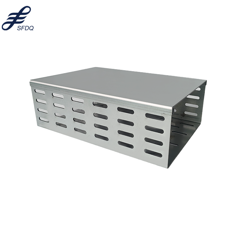
A cable bridge represents one of the most elegant and efficient structural solutions in modern engineering, combining aesthetic appeal with exceptional load-bearing capability. When designing a cable bridge, engineers must carefully balance multiple technical, environmental, and safety considerations to create a structure that endures decades of use. The foundation of any successful cable bridge lies in comprehensive planning, precise calculations, and understanding how forces distribute throughout the entire system. This guide explores the essential principles and practices for designing a cable bridge that meets rigorous safety standards while delivering reliable performance in challenging environments.
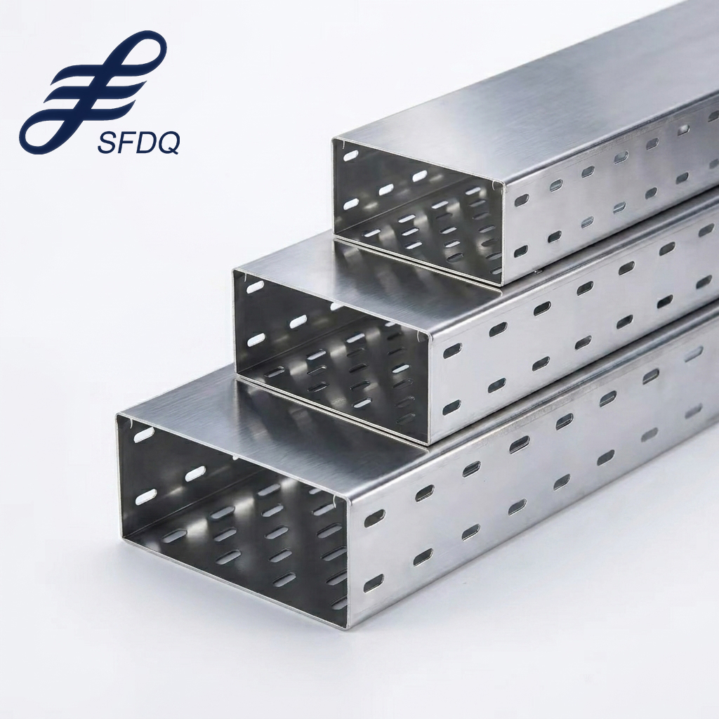
Designing a cable bridge involves coordinating structural systems, material specifications, and installation procedures into a cohesive framework that prioritizes safety, longevity, and operational efficiency. The support structure of a cable bridge must withstand dynamic loads, environmental stresses, and potential maintenance challenges over many years. Modern cable bridge design integrates advanced computational analysis with field-tested engineering practices to optimize performance across all operational scenarios. Understanding these fundamentals helps stakeholders make informed decisions about infrastructure investments and ensure their installations perform reliably throughout their intended lifespan.
Fundamental Design Principles for Cable Bridge Structures
Load Distribution and Force Analysis
Designing a cable bridge begins with thorough analysis of how loads transfer through the system from their point of application to the support foundations. The primary cables in a cable bridge carry tension loads that distribute forces along the entire span, reducing concentrated stress at any single point. Engineers must calculate dead loads (permanent weight of materials), live loads (people, equipment, vehicles), and dynamic loads (wind, vibration, seismic activity) when analyzing a cable bridge structure. Proper cable bridge design requires understanding how each load type interacts with the overall system and where stress concentrations might develop. Advanced finite element analysis tools enable designers to simulate real-world conditions and validate that a cable bridge will perform safely under anticipated service conditions.
Material Selection and Durability Considerations
Selecting appropriate materials forms a critical foundation for long-term cable bridge performance and reliability. High-strength steel cables are standard in cable bridge design because they offer excellent tensile strength while remaining relatively lightweight compared to their load capacity. The support structure of a cable bridge typically combines steel components with concrete, aluminum, or composite materials depending on environmental exposure and aesthetic requirements. When designing a cable bridge, engineers must evaluate corrosion resistance, fatigue characteristics, and environmental compatibility to ensure the structure remains durable through decades of operation. Material redundancy and strategic protective coatings substantially improve the long-term viability of any cable bridge installation in aggressive environments such as coastal regions or industrial areas.
Key Structural Components and Support Systems
Anchor Points and Foundation Engineering
The anchor points represent perhaps the most critical component in any cable bridge design, as they ultimately transfer all structural loads into the earth or bedrock. Designing a cable bridge requires massive anchor blocks, typically constructed from reinforced concrete, that can resist the enormous tension forces generated by suspended cables. The support structure of a cable bridge depends entirely on adequate foundation preparation, geological investigation, and precise anchor installation to prevent catastrophic failure. Engineers designing a cable bridge must verify that geological conditions can accommodate required anchor depths and bearing capacities without exceeding soil strength limits. Inadequate anchorage remains one of the most common causes of cable bridge structural failure, making this component worthy of investment in comprehensive geotechnical studies and conservative design margins.
Tower and Pylon Design Strategy
Cable bridge towers must maintain vertical alignment while accommodating horizontal forces, temperature-induced movement, and dynamic loads without excessive deflection. Designing a cable bridge tower involves calculating the optimal geometry that minimizes material consumption while maintaining structural rigidity and aesthetic proportions. The support structure of a cable bridge typically features towers designed to distribute cable tensions into vertical compression loads that transfer safely to the foundation. Modern cable bridge design often employs aerodynamic tower profiles that reduce wind loading and vibration while maintaining sufficient cross-sectional area for structural efficiency. Symmetrical tower design improves load distribution and reduces the potential for unbalanced stresses that could compromise the integrity of a cable bridge during unusual loading scenarios.
Installation, Testing, and Performance Validation
Sequencing and Temporary Support Requirements
Successfully constructing a cable bridge requires carefully orchestrated sequencing that installs major components in an optimal order while maintaining structural stability throughout the construction phase. Designing a cable bridge includes planning for temporary bracing systems that stabilize the structure before cables assume their designed loads. The support structure of a cable bridge must incorporate provisions for staged cable tensioning that gradually transfers loads as each cable section reaches full installation. Engineers designing a cable bridge develop detailed installation procedures that account for material handling, worker safety, and equipment positioning to maintain schedule and budget objectives. Quality control checkpoints throughout construction ensure that field conditions match design assumptions and that any discovered discrepancies receive prompt remediation before they compromise the overall cable bridge integrity.
Load Testing and Performance Monitoring
Comprehensive load testing validates that a cable bridge performs according to design expectations and provides baseline performance data for ongoing maintenance programs. Designing a cable bridge includes specifications for post-installation testing that measures deflections, cable tensions, and dynamic responses under controlled loading conditions. The support structure of a cable bridge should demonstrate predictable behavior during load testing, confirming that material properties, installation quality, and design assumptions align with actual field conditions. Permanent monitoring systems installed within cable bridge structures provide real-time data on cable tensions, temperature effects, and environmental loading patterns. This performance data proves invaluable for optimizing maintenance schedules, planning future upgrades, and validating the service life assumptions incorporated into the original cable bridge design.
FAQ
What environmental factors most significantly impact cable bridge design and longevity?
Environmental factors including corrosive salt spray, temperature extremes, wind patterns, and seismic activity substantially influence cable bridge design decisions and material selections. Coastal installations require enhanced corrosion protection for all steel components in a cable bridge system, typically involving specialized coatings, stainless steel fasteners, and sacrificial anodes. Temperature cycling causes expansion and contraction in cable bridge materials, requiring expansion joints and sliding bearings that accommodate movement without introducing damaging stresses. Wind exposure demands careful aerodynamic analysis when designing a cable bridge, as oscillatory wind loads can trigger resonance in insufficiently damped structures. Engineers designing a cable bridge must conduct comprehensive environmental assessments specific to the installation location to ensure that material selections and structural details provide adequate protection throughout the intended design life.
How do cable bridges compare to traditional beam bridge designs in terms of structural efficiency?
Cable bridges achieve superior span-to-weight ratios compared to conventional beam bridges because cables work primarily in tension, utilizing high-strength materials most efficiently. A cable bridge can economically span distances where comparable beam structures would require prohibitive material quantities and excessive dead weight. The support structure of a cable bridge distributes loads across flexible cables rather than concentrating them at intermediate supports, reducing localized stress concentrations. For long spans exceeding approximately 300 meters, cable bridge designs typically prove more economical than alternative structural systems when considering total material cost, environmental impact, and construction logistics. Designing a cable bridge for any specific application requires comparative analysis against candidate solutions to confirm that the cable solution genuinely offers advantages justifying its typically greater complexity and specialized construction requirements.
What maintenance and inspection protocols should operators implement for cable bridges?
Effective cable bridge maintenance begins with detailed inspection protocols that systematically examine all structural components, focusing particularly on cable condition, corrosion indicators, and bolt integrity. Designing a cable bridge includes specifications for access systems and inspection points that enable thorough examination of critical areas without requiring expensive and disruptive construction activities. Regular cable bridge inspections should occur at prescribed intervals, typically annually for general assessment and every three to five years for comprehensive detailed inspection including ultrasonic thickness measurements. Maintenance activities for a cable bridge should include coating reapplication, bolt retensioning, bearing replacement, and drainage system cleaning to prevent water accumulation and accelerated corrosion. Documentation systems that track all cable bridge maintenance activities, inspection findings, and remedial actions create valuable historical records that inform future planning and demonstrate due diligence in system stewardship.