

Planning an effective cable tray layout is crucial for any industrial or commercial facility that requires organized cable management systems. Cable trays serve as the backbone of electrical infrastructure, providing secure pathways for power, data, and communication cables throughout buildings and industrial complexes. A well-designed cable tray system ensures optimal performance, safety compliance, and long-term maintenance efficiency while reducing installation costs and minimizing operational disruptions.
The foundation of successful cable tray installation begins with comprehensive planning that considers current electrical needs and future expansion requirements. Modern facilities demand sophisticated cable management solutions that can accommodate increasing power loads, additional data circuits, and emerging technologies. Without proper planning, cable installations often become disorganized, leading to maintenance challenges, safety hazards, and costly retrofitting projects that could have been avoided through strategic initial design.
Understanding Cable Tray Types and Applications
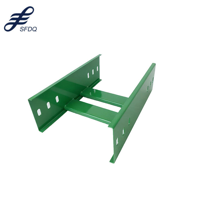
Ladder Type Cable Trays for Heavy-Duty Applications
Ladder type cable trays represent the most common choice for industrial facilities due to their exceptional strength and ventilation properties. These cable trays feature two parallel side rails connected by rungs, creating an open structure that allows excellent airflow around cables while providing robust support for heavy electrical loads. The ladder design makes cable installation and maintenance straightforward, as technicians can easily access individual cables without disturbing the entire bundle.
Industrial facilities typically utilize ladder cable trays for main distribution runs where large quantities of power cables require secure routing. Manufacturing plants, data centers, and chemical processing facilities rely on these systems to manage high-voltage feeders, motor circuits, and control wiring. The open construction prevents heat buildup that could degrade cable insulation, extending system lifespan and improving reliability in demanding environments.
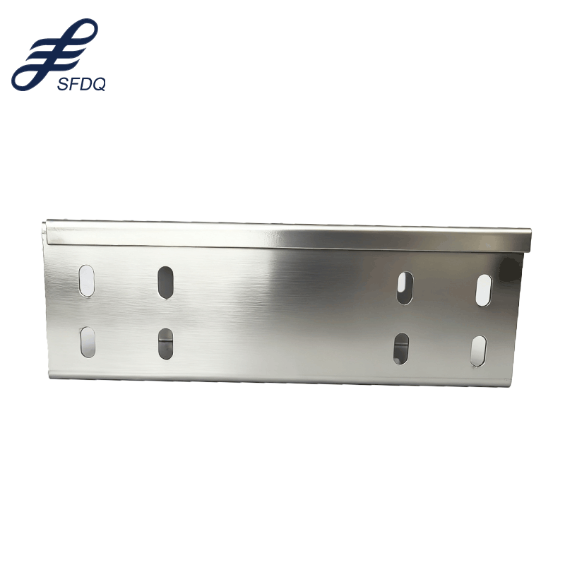
Perforated Cable Trays for Versatile Installation
Perforated cable trays offer a balanced solution between the open design of ladder trays and the complete enclosure of solid bottom systems. The perforated bottom provides additional cable support while maintaining ventilation capabilities essential for heat dissipation. These cable trays excel in applications requiring moderate cable support with enhanced protection against debris and environmental contaminants.
Commercial buildings and office complexes frequently specify perforated cable trays for telecommunications and low-voltage power distribution. The perforations allow for tie-wrapping cables directly to the tray bottom, creating neat installations that meet aesthetic requirements while maintaining functional performance. This design flexibility makes perforated systems ideal for areas where cable organization and appearance matter significantly.
Load Calculations and Structural Requirements
Determining Cable Weight and Fill Ratios
Accurate load calculations form the cornerstone of safe cable tray design, requiring detailed analysis of cable weights, quantities, and distribution patterns. Engineers must calculate both the static load from installed cables and dynamic loads from maintenance activities, thermal expansion, and seismic forces. Cable trays must support these loads with appropriate safety factors while maintaining structural integrity throughout their operational lifespan.
Fill ratio calculations ensure that cable trays operate within safe capacity limits while allowing for future expansion. Industry standards typically recommend maximum fill ratios of 50% for single-layer installations and 25% for multi-layer configurations. These guidelines prevent overcrowding that could impede heat dissipation, complicate maintenance procedures, or exceed the structural capacity of the tray system.
Support Spacing and Structural Design
Proper support spacing ensures that cable trays maintain structural integrity under maximum design loads while minimizing deflection that could stress cables or create installation difficulties. Support spacing requirements vary based on tray type, width, loading conditions, and environmental factors such as temperature variations and seismic activity. Ladder cable trays typically require closer support spacing than solid bottom systems due to their open construction.
Structural support systems must accommodate both vertical and horizontal forces, including cable pulling tensions during installation and maintenance activities. Seismic regions require special consideration for lateral bracing and flexible connections that allow movement while maintaining system integrity. The support structure design should also facilitate future modifications and expansions without requiring major reconstruction of the existing installation.
Routing and Pathway Planning Strategies
Horizontal Distribution Planning
Horizontal cable tray routing requires careful coordination with other building systems including HVAC ductwork, plumbing, fire protection systems, and structural elements. Effective planning establishes clear pathways that minimize conflicts while maintaining adequate clearances for maintenance access. The routing strategy should consider both current installation requirements and future expansion possibilities to avoid costly modifications later.
Main distribution cable trays typically follow building corridors or designated utility zones that provide direct paths between electrical rooms and load centers. Branch circuits require careful planning to minimize cable lengths while maintaining organized distribution patterns. The horizontal layout should incorporate appropriate expansion joints and supports to accommodate thermal movement and building settling over time.
Vertical Rise and Drop Considerations
Vertical cable tray installations present unique challenges related to cable support, access, and safety requirements. Vertical runs require specialized support methods to prevent cable stress and ensure proper weight distribution throughout the system height. Cable trays in vertical applications must incorporate appropriate cable restraints to prevent movement during thermal cycling or seismic events.
Planning vertical installations requires coordination with fire stopping requirements, ensuring that penetrations through floor and wall assemblies maintain building fire ratings. Vertical cable trays often require closer support spacing and enhanced structural connections to accommodate the additional loads from cable weight and dynamic forces. Access considerations become critical for maintenance activities, requiring appropriate platforms or access provisions for safe servicing.
Code Compliance and Safety Standards
National Electrical Code Requirements
National Electrical Code compliance ensures that cable tray installations meet minimum safety standards for electrical installations in commercial and industrial facilities. NEC Article 392 specifically addresses cable tray requirements including construction standards, installation methods, and cable fill limitations. Understanding these requirements early in the planning process prevents costly modifications during construction and ensures inspection approval.
Fire resistance requirements significantly impact cable tray selection and installation methods, particularly in critical facilities and high-occupancy buildings. Cable trays must maintain structural integrity during fire events to support emergency circuits and facilitate safe evacuation. Some installations require fire-rated cable trays or additional fire protection measures to meet building code requirements and insurance specifications.
Local Building Codes and Standards
Local building codes often impose additional requirements beyond national standards, addressing regional concerns such as seismic activity, environmental conditions, and specific occupancy types. Understanding local code requirements early in the design process prevents delays and ensures that cable tray installations receive prompt approval from building officials and inspection authorities.
Seismic requirements significantly impact cable tray design in earthquake-prone regions, requiring enhanced bracing and flexible connections that allow movement while maintaining system integrity. Coastal installations may require corrosion-resistant materials and protective coatings to withstand harsh environmental conditions. Industrial facilities often face additional requirements related to hazardous locations, explosion-proof installations, and chemical resistance specifications.
Installation Best Practices and Techniques
Pre-Installation Planning and Coordination
Successful cable tray installation begins with comprehensive pre-installation planning that coordinates all trades and identifies potential conflicts before construction begins. This planning phase should include detailed shop drawings, material takeoffs, and installation sequences that optimize construction efficiency while maintaining quality standards. Early coordination prevents costly delays and ensures that cable trays integrate properly with other building systems.
Material handling and storage requirements for cable trays demand careful consideration due to their size and weight characteristics. Proper storage prevents damage from weather exposure and construction activities while ensuring materials remain accessible for installation crews. The installation sequence should coordinate cable tray installation with other trades to maximize efficiency and minimize interference with ongoing construction activities.
Quality Control and Testing Procedures
Quality control procedures ensure that cable tray installations meet design specifications and safety requirements throughout the construction process. Regular inspections should verify proper support spacing, load distribution, grounding connections, and compliance with applicable codes and standards. Documentation of these inspections provides valuable records for commissioning and future maintenance activities.
Testing procedures for cable tray systems focus on structural integrity, electrical continuity, and grounding effectiveness. Load testing may be required for critical installations or unusual loading conditions to verify that the system performs as designed. Proper documentation of testing results provides confidence in system performance and creates baseline data for future maintenance and expansion projects.
Maintenance and Long-Term Operation
Preventive Maintenance Programs
Preventive maintenance programs extend cable tray system lifespan while ensuring continued safe and reliable operation throughout the facility lifecycle. Regular inspection schedules should address structural integrity, corrosion protection, and cable organization to identify potential problems before they create safety hazards or operational disruptions. Maintenance programs should also verify that cable loading remains within design limits as systems expand over time.
Corrosion monitoring becomes particularly important for cable trays in harsh environments or outdoor installations where exposure to moisture, chemicals, or salt air can accelerate deterioration. Regular cleaning procedures remove debris and contaminants that could trap moisture or create fire hazards. Protective coating maintenance ensures long-term corrosion resistance and maintains the aesthetic appearance of visible installations.
Future Expansion Planning
Future expansion planning ensures that cable tray systems can accommodate growing electrical demands without requiring major modifications or replacements. Initial designs should incorporate spare capacity and expansion provisions that allow for orderly growth while maintaining system organization and performance. Planning for future needs prevents overcrowding and maintains efficient maintenance access throughout the system lifecycle.
Technology evolution continues to impact cable tray requirements as facilities adopt new systems for automation, communications, and energy management. Cable trays must accommodate changing cable types, sizes, and quantities while maintaining compatibility with existing installations. Flexible design approaches allow facilities to adapt to new requirements without compromising existing system performance or safety.
FAQ
What factors determine the appropriate cable tray width for my application
Cable tray width selection depends on the number and size of cables, required fill ratios, and future expansion needs. Standard widths range from 6 inches to 36 inches, with larger custom sizes available for special applications. Consider both current cable quantities and anticipated growth to ensure adequate capacity while avoiding oversized installations that waste space and increase costs.
How do I calculate the proper support spacing for cable trays
Support spacing calculations consider tray type, width, loading conditions, and deflection limits specified in industry standards. Ladder cable trays typically require supports every 8 to 12 feet, while solid bottom trays may need closer spacing depending on loading. Consult manufacturer specifications and structural engineering requirements to determine appropriate spacing for your specific installation conditions.
What are the key differences between aluminum and steel cable trays
Steel cable trays offer superior strength and fire resistance at lower initial cost, making them suitable for heavy-duty industrial applications. Aluminum trays provide excellent corrosion resistance and lighter weight, reducing installation labor and support requirements in corrosive environments. Material selection should consider environmental conditions, loading requirements, and lifecycle costs including maintenance and replacement considerations.
How do cable trays integrate with fire protection systems
Cable tray fire protection integration requires coordination with sprinkler systems, fire stopping materials, and emergency power requirements. Fire-rated cable trays or protective coatings may be necessary in critical areas to maintain circuit integrity during fire events. Proper installation maintains fire separations between different voltage levels and ensures that emergency systems remain operational when needed most.