 EN
EN


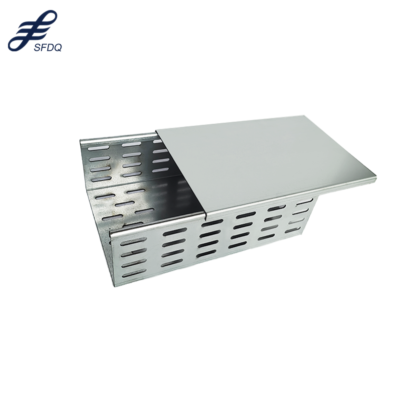
A cable bridge is a structural support system designed to carry electrical cables, data lines, and fiber optic connections across large distances while maintaining organizational integrity and accessibility. Unlike traditional conduit systems buried underground or mounted directly to walls, a cable bridge provides an elevated pathway that spans openings between buildings, across machinery areas, over production floors, and through complex industrial environments. The cable bridge serves as the backbone of modern industrial infrastructure, enabling organizations to manage thousands of individual conductors while maintaining safety standards and operational flexibility.
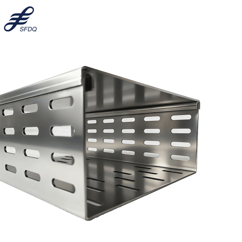
The significance of a cable bridge extends beyond simple cable routing. In manufacturing plants, data centers, and facilities with extensive electrical systems, a cable bridge reduces installation time, simplifies maintenance access, and protects cables from physical damage. The cable bridge design allows technicians to add, remove, or modify cable runs without disrupting existing infrastructure, making it invaluable for dynamic industrial environments where system upgrades occur frequently.
Understanding Cable Bridge Design and Construction
Structural Framework and Material Composition
A cable bridge is constructed using materials selected for durability, weight capacity, and environmental resistance. Steel cable bridges offer maximum strength and are preferred in heavy-load applications where hundreds of cables must be supported simultaneously. Aluminum cable bridges provide lightweight alternatives ideal for facilities where weight distribution matters or where corrosion resistance is essential. The cable bridge framework typically includes longitudinal support beams, lateral bracing, and attachment points engineered to distribute load evenly across the span.
The cable bridge structure must accommodate not only the static weight of installed cables but also dynamic forces from thermal expansion, vibration, and installation activities. Engineering specifications for a cable bridge include load ratings measured in pounds per linear foot, span distances, and deflection limits. Manufacturers design each cable bridge system with safety factors built in, ensuring that even under adverse conditions, the cable bridge maintains structural integrity and protects the critical infrastructure it supports.
Spanning Mechanisms and Support Systems
The ability of a cable bridge to span large distances depends on intermediate support points strategically positioned throughout the installation area. A cable bridge typically requires support columns or mounting structures at intervals determined by the total cable load and material strength. The cable bridge spanning distance between supports can range from ten feet to over thirty feet, depending on design specifications and load requirements. Engineers calculate the cable bridge span by considering material deflection, safety margins, and the total weight of cables anticipated in the system.
A cable bridge achieves its long-distance capability through careful geometric design, where the cable bridge profile may incorporate reinforced sections, varying cross-sectional areas, or composite construction techniques. Suspension elements within the cable bridge distribution system help manage lateral movement and prevent sagging. The cable bridge installation methodology ensures that each support point is properly secured to building structures, equipment racks, or free-standing pedestals, creating a unified system that maintains consistent elevation and alignment across the entire span.
Applications and Industry Implementation
Manufacturing and Production Environments
In manufacturing facilities, a cable bridge routes power cables, control lines, and communication systems throughout sprawling production areas. The cable bridge enables factories to organize hundreds of electrical connections without creating fire hazards or tripping obstacles on the floor. A cable bridge in manufacturing environments can span from control rooms across production floors to individual machines, supporting the integrated automation systems that modern plants require. The cable bridge accessibility allows maintenance teams to troubleshoot electrical problems quickly by providing clear visual routing of all conductors.
The cable bridge installation in factories often accommodates future expansion, with each cable bridge section designed to accept additional cables as production lines evolve. A cable bridge system supports both permanent installations and temporary connections for seasonal or project-based operations, making it essential infrastructure for adaptable manufacturing environments.
Data Centers and IT Infrastructure
Data centers depend on cable bridge systems to manage thousands of fiber optic and copper connections while maintaining optimal airflow and thermal management. The cable bridge routes cables horizontally above server racks and vertically between floor levels, creating organized pathways that prevent cable congestion. A cable bridge in data center applications must handle high cable density while allowing unrestricted access for installation, maintenance, and replacement activities. The cable bridge design in these facilities often incorporates special considerations for fire suppression systems, emergency protocols, and regulatory compliance requirements specific to technology infrastructure.
Utility and Infrastructure Projects
Utilities deploy cable bridge systems to span utility corridors, cross roads, and bridge large distances between substations and distribution points. The cable bridge allows utilities to organize power transmission lines, telecommunications cables, and monitoring systems within a single integrated structure. A cable bridge spanning utility corridors eliminates the need for multiple parallel conduit systems and simplifies maintenance access. The cable bridge construction for utility applications often requires specialized engineering to withstand environmental conditions, including wind loading, ice accumulation, and temperature variations across seasons.
Installation Considerations and Best Practices
Planning and Site Assessment
Successful cable bridge installation begins with comprehensive site assessment to determine optimal routing paths, support point locations, and load requirements. Engineers evaluate the cable bridge route for obstacles, clearance restrictions, and accessibility needs before finalizing placement. The cable bridge design must account for future growth, with sizing calculations that often include twenty to thirty percent capacity buffer. A cable bridge project timeline includes structural load calculations, support point engineering, and coordination with building infrastructure teams to ensure proper integration.
The cable bridge installation requires detailed documentation mapping cable routes, termination points, and load distribution. Planning software helps visualize the cable bridge layout, identify potential conflicts with existing infrastructure, and optimize support point spacing to minimize material costs while maintaining adequate load capacity.
Maintenance and Long-Term Performance
A cable bridge system requires periodic inspection to verify structural integrity, check fastener tightness, and assess for corrosion or material degradation. The cable bridge maintenance program includes visual inspections for cable damage, proper support alignment, and unauthorized modifications. Regular cable bridge maintenance prevents issues that could compromise cable protection or create fire hazards. The cable bridge longevity depends on environmental conditions, with outdoor installations requiring protective coatings and indoor cable bridge systems benefiting from ventilation and moisture control measures.
The cable bridge performance monitoring involves checking deflection measurements at loaded sections, verifying that the cable bridge has not shifted or settled, and confirming that cable management organization remains optimized. Professional cable bridge inspection services document system condition and recommend upgrades or reinforcements when load requirements change.
FAQ
What is the maximum distance a cable bridge can span?
The maximum span distance for a cable bridge depends on the material, cross-sectional design, and anticipated cable load. Most industrial cable bridge systems span between ten and thirty feet between support points, though specialized engineering can extend spans to forty feet or beyond. The cable bridge span calculation balances load capacity with acceptable deflection limits, typically keeping deflection under half an inch over the span distance. Heavier cable concentrations require shorter cable bridge spans and more frequent support points.
How does a cable bridge differ from cable conduit systems?
A cable bridge provides open tray routing with accessibility advantages, while cable conduit completely encloses wires for maximum protection. The cable bridge allows technicians to add or remove individual cables without disturbing the entire system, whereas conduit requires pulling cables through confined spaces. A cable bridge installation typically costs less than comprehensive conduit systems and requires less maintenance. Cable bridge systems work best in controlled environments, while conduit provides superior protection in harsh or exposed outdoor conditions.
What materials are best for outdoor cable bridge applications?
Outdoor cable bridge installations typically use aluminum or stainless steel constructions due to superior corrosion resistance. Aluminum cable bridge systems offer lightweight characteristics and inherent oxidation protection, making them ideal for coastal or chemically aggressive environments. Stainless steel cable bridge designs provide maximum durability but at higher material cost. Cable bridge systems in outdoor applications benefit from protective coatings, proper drainage design to prevent water pooling, and elevated installation to minimize ground moisture exposure.