

Modern electrical installations require systematic cable management solutions that combine functionality, safety, and cost-effectiveness. A perforated cable tray represents one of the most versatile and widely adopted cable support systems in industrial, commercial, and residential applications. These specialized cable management systems feature strategically placed holes that provide exceptional ventilation while maintaining structural integrity and easy cable access throughout the installation process.
The installation of a perforated cable tray system requires careful planning, proper preparation, and adherence to industry standards to ensure optimal performance and longevity. Understanding the fundamental principles of tray installation, from initial site assessment to final cable placement, enables electrical professionals to create robust cable management infrastructures that meet demanding operational requirements while facilitating future maintenance and expansion needs.
Understanding Perforated Cable Tray Systems
Design Characteristics and Benefits
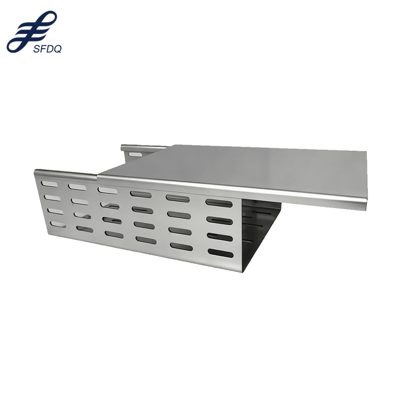
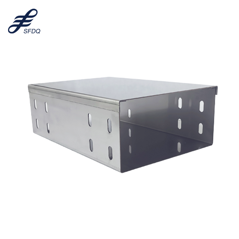
A perforated cable tray features a unique design incorporating numerous holes across its base and sides, creating superior airflow characteristics compared to solid bottom alternatives. The perforation pattern typically follows standardized specifications that balance structural strength with ventilation efficiency, allowing heat dissipation from power cables while preventing cable overheating in high-density installations. This design approach significantly reduces the risk of thermal damage to sensitive electrical components.
The hole pattern in a perforated cable tray also facilitates easy cable routing and branch connections at any point along the tray run. Electrical contractors appreciate this flexibility because it eliminates the need for specialized fittings when adding new circuits or modifying existing cable paths. The perforations additionally reduce the overall weight of the tray system while maintaining adequate load-bearing capacity for typical cable installations.
Material Selection and Durability Factors
Steel construction remains the most common material choice for perforated cable tray applications, offering excellent strength-to-weight ratios and cost-effectiveness for standard indoor environments. Galvanized steel provides enhanced corrosion resistance, making it suitable for moderate moisture conditions and industrial facilities with controlled atmospheric conditions. The galvanization process creates a protective zinc coating that extends service life significantly.
Stainless steel variants of perforated cable tray systems excel in harsh environmental conditions, including chemical processing plants, marine installations, and food processing facilities where corrosion resistance is paramount. The superior corrosion resistance of stainless steel justifies its higher initial cost through reduced maintenance requirements and extended service life, particularly in applications involving exposure to aggressive chemicals or high humidity levels.
Pre-Installation Planning and Assessment
Site Survey and Load Calculations
Comprehensive site assessment forms the foundation of successful perforated cable tray installation, requiring detailed evaluation of cable routing requirements, environmental conditions, and structural support availability. Professional installers conduct thorough load calculations considering the weight of cables, future expansion possibilities, and dynamic loading factors such as seismic activity or vibration sources that might affect the installation over time.
The calculation process for a perforated cable tray installation must account for the distributed weight of cables across the tray length, concentrated loads at support points, and safety factors specified by local electrical codes. These calculations determine appropriate tray sizes, support spacing intervals, and mounting hardware requirements to ensure structural integrity throughout the system's operational life while maintaining compliance with applicable safety standards.
Code Compliance and Regulatory Requirements
National Electrical Code (NEC) provisions govern perforated cable tray installations in the United States, specifying requirements for cable types, support methods, grounding provisions, and installation clearances. Understanding these regulatory requirements prevents costly rework and ensures safe operation of the electrical system. Local amendments to national codes may impose additional requirements specific to regional conditions or applications.
International installations must comply with IEC standards or local electrical codes that may differ significantly from NEC requirements. The selection of appropriate cable types for use with a perforated cable tray system depends on environmental conditions, voltage ratings, and specific code requirements that vary by jurisdiction and application type.
Installation Techniques and Best Practices
Support Structure Preparation
Proper support structure preparation ensures long-term reliability of the perforated cable tray system and prevents structural failures that could damage expensive cables or create safety hazards. Support brackets must be securely anchored to building structural elements using appropriate fasteners rated for the calculated loads, with particular attention to concrete anchor specifications in masonry construction applications.
The spacing of support points for a perforated cable tray installation depends on tray width, expected cable load, and material specifications provided by the manufacturer. Typical support spacing ranges from 4 to 12 feet for standard installations, with closer spacing required for heavily loaded trays or applications involving significant vibration or seismic activity that could stress the mounting system.
Tray Assembly and Connection Methods
Sequential assembly of perforated cable tray sections requires careful attention to alignment and connection integrity to maintain structural continuity throughout the system. Mechanical connections between tray sections utilize specialized splice plates and bolted joints that ensure electrical continuity for grounding purposes while providing adequate mechanical strength to resist operational stresses and thermal expansion forces.
The connection process for a perforated cable tray system involves precise measurement, proper gasket installation where required, and uniform torque application to prevent joint loosening over time. Expansion joints accommodate thermal movement in long tray runs, preventing stress concentration that could lead to joint failure or tray deformation under temperature cycling conditions.
Cable Installation and Management
Cable Laying Techniques
Systematic cable installation in a perforated cable tray requires adherence to manufacturer specifications regarding cable bend radius, pulling tensions, and layer arrangements to prevent damage during installation and ensure optimal performance throughout the cable's service life. Power cables and control cables often require segregation to minimize electromagnetic interference and comply with electrical code requirements for cable separation.
The perforation pattern in the tray facilitates cable support at regular intervals, reducing the risk of cable sag or deformation under gravitational loads. Proper cable dressing techniques ensure uniform distribution of cable weight across the perforated cable tray width while maintaining adequate clearance for ventilation and future cable additions or modifications.
Cable Securing and Support Methods
Cable tie applications in perforated cable tray installations require careful selection of tie materials and installation methods to prevent cable damage while providing adequate support against movement during system operation. Stainless steel cable ties offer superior durability in industrial environments, while nylon ties provide cost-effective solutions for standard applications with moderate environmental exposure.
The frequency of cable securing points depends on cable type, size, and installation orientation, with vertical runs requiring closer tie spacing to prevent excessive cable stress at support points. Proper cable identification and labeling facilitate future maintenance and troubleshooting activities while ensuring compliance with electrical code requirements for cable marking and documentation.
Quality Assurance and Testing Procedures
Installation Inspection Protocols
Comprehensive inspection of completed perforated cable tray installations verifies compliance with design specifications, code requirements, and manufacturer recommendations before cable installation begins. Visual inspection identifies potential issues such as improper support spacing, inadequate grounding connections, or mechanical damage that could compromise system performance or safety during operation.
Mechanical testing of support connections ensures adequate load-bearing capacity and joint integrity throughout the perforated cable tray system. Load testing protocols verify that installed supports can accommodate design loads with appropriate safety margins, while continuity testing confirms proper electrical grounding throughout the system for personnel safety and equipment protection.
Documentation and Compliance Verification
Proper documentation of perforated cable tray installations includes detailed drawings showing tray routing, support locations, cable assignments, and any deviations from original design specifications. This documentation serves as a valuable reference for future maintenance activities and provides essential information for electrical inspectors reviewing the installation for code compliance and safety verification.
Compliance verification involves systematic review of installation practices against applicable electrical codes, manufacturer specifications, and project requirements to ensure safe and reliable operation. The verification process includes confirmation of proper cable types, adequate clearances, appropriate grounding methods, and compliance with any special requirements for the specific application or environment where the perforated cable tray system is installed.
Maintenance and Long-term Performance
Preventive Maintenance Strategies
Regular maintenance of perforated cable tray systems extends service life and prevents unexpected failures that could disrupt critical electrical systems. Maintenance protocols include periodic inspection of support connections, assessment of corrosion protection effectiveness, and verification of cable condition within the tray system to identify potential issues before they become serious problems requiring extensive repairs or replacement.
The perforated design of these cable tray systems facilitates maintenance access while providing natural ventilation that reduces maintenance requirements compared to enclosed cable management systems. Regular cleaning removes accumulated debris that could impede ventilation or create fire hazards, while inspection of cable ties and support hardware ensures continued mechanical integrity of the installation.
Expansion and Modification Considerations
Future expansion capabilities represent a significant advantage of perforated cable tray systems, allowing easy addition of new cables without major modifications to the existing infrastructure. The perforation pattern enables cable routing at any point along the tray length, facilitating branch connections and equipment relocations with minimal disruption to existing electrical systems operating within the facility.
Modification procedures for perforated cable tray installations require careful planning to maintain structural integrity and code compliance while accommodating changing electrical system requirements. The flexibility inherent in these tray systems supports cost-effective facility modifications and expansions that would be significantly more expensive with alternative cable management approaches.
FAQ
What are the primary advantages of using perforated cable tray systems over solid bottom alternatives
Perforated cable tray systems offer superior ventilation characteristics that prevent cable overheating in high-density installations, while the hole pattern facilitates easy cable routing and branch connections at any point along the tray run. The perforations also reduce overall system weight and provide excellent access for maintenance and future cable additions, making them more versatile and cost-effective than solid alternatives for most applications.
How do I determine the appropriate support spacing for my perforated cable tray installation
Support spacing for perforated cable tray systems depends on tray width, expected cable load, environmental conditions, and manufacturer specifications, typically ranging from 4 to 12 feet for standard installations. Heavily loaded trays or applications involving significant vibration require closer support spacing, while the specific requirements should be calculated based on total cable weight, dynamic loading factors, and applicable safety codes for your installation location.
What cable types are suitable for installation in perforated cable tray systems
Most standard electrical cables including power cables, control cables, and instrumentation cables are suitable for perforated cable tray installation, provided they meet NEC Article 392 requirements or applicable local electrical codes. Cable selection depends on voltage rating, environmental conditions, and specific application requirements, with some installations requiring cables with enhanced flame retardant properties or special jacketing materials for harsh environmental conditions.
How should I maintain and inspect my perforated cable tray system for optimal performance
Regular maintenance of perforated cable tray systems includes periodic visual inspection of support connections, assessment of corrosion protection, verification of cable condition, and removal of accumulated debris that could impede ventilation. Inspection frequency typically ranges from annual to quarterly depending on environmental conditions, with more frequent inspections required in harsh industrial environments or outdoor installations exposed to weather and environmental contaminants.
Table of Contents
- Understanding Perforated Cable Tray Systems
- Pre-Installation Planning and Assessment
- Installation Techniques and Best Practices
- Cable Installation and Management
- Quality Assurance and Testing Procedures
- Maintenance and Long-term Performance
-
FAQ
- What are the primary advantages of using perforated cable tray systems over solid bottom alternatives
- How do I determine the appropriate support spacing for my perforated cable tray installation
- What cable types are suitable for installation in perforated cable tray systems
- How should I maintain and inspect my perforated cable tray system for optimal performance